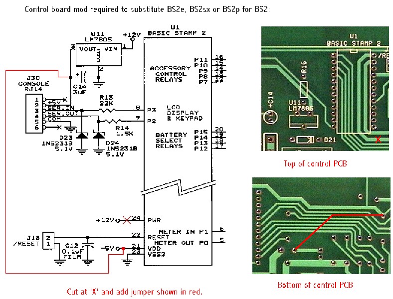
Substituting a BS2e, BS2sx or BS2p for the BS2 requires a small hardware modification
to the control board. The plain BS2 can accept supply voltages on its PWR
pin (pin 24) in the 5.5-15VDC range, however, the newer and more powerful
models can only accept 5.5-12VDC (7.5VDC recommended). The original control
board design applies the unregulated accessory battery voltage to pin 24 of
the Stamp, however, this voltage can easily approach 15VDC. A solution is
to disconnect U1, pin 24 from the "12V" supply, and add a jumper from U1,
pin 21 (VDD) to U11, pin 3 (the output of the LM7805 5V regulator). This
leaves the Stamp (U1) and the control board's 5V rail powered from U11 rather
than the Stamp's onboard 5V regulator. Here is an
image(136kb JPG) showing exactly what to do.
The Orcad library had the the wrong pinouts for the ULN200n chip. They are a mirror image of the correct pinouts. To fix this, you must either mount the ULN2001 on the bottom of the board, or fold the chip's pins up instead of down, and then put it on the top of the board.
[NOTE that the pinouts of the ULN200x's (U4,5,6) on the schematic is also incorrect (i.e. consistent with the Orcad library's mirror-image pinout). So, when examining the schematic, one must mentally correct for the pin labelled P8 on the schematic is actually P1, etc.]
I use a Vicor BatMod for my DC/DC converter, mounted to the BOTTOM of the Balancer control board. The control board itself is then mounted on standoffs to a thick aluminum plate, which serves as the heatsink for the BatMod and bridge rectifier D30 (also mounted on the BOTTOM of the board).
[Lee also noted that he used 1/2" standoffs between the control board and the aluminum base to which it was mounted; Fred Whitridge reports that, unless one is scrupulous about dressing the leads on the top-mounted components, 5/8" standoffs (as he is using) may be easier.]
I noticed that [the holes for the Vicor module pins are a wee bit too small], too. The mistake was that I specified the drill size for the Batmod holes. They drilled it this size, but then put the plated-thru hole in it, which decreased the diameter. On mine, I drilled out the holes very slightly, and pressed the BatMod into place.
Or, you can cut out the BatMod section of the board on the white lines, and mount the BatMod and its section of PC board remotely, on a heatsink.
Or, if you want a more powerful DC/DC, you can use two or more Batmods in parallel. In this case, the first BatMod is mounted normally on the control board. The second BatMod mounts on a section cut out of a second control board (from someone who doesn't use the BatMod), and you use it for the second BatMod. 0.25" fast-on connectors provide all the connections between the two BatMods.
Or, you can leave all these parts off, and use an external DC/DC like a Todd PC30, etc.
I hadn't picked the actual part when I laid out the board, and allowed enough holes so anything I found should fit. I guessed wrong!
Note that it doesn't quite fit the holes in the board - the easiest way is to snip the plastic base that holds its wires so you can fit them into the holes on the PC board.
PS: I also put glue between it and the PC board since it is a moderately heavy part and the lead wires are so thin.
C16 was a capacitor I had to add for stability after the board was laid out. Solder it between Q1's base and collector. It should be shown on your schematic.
Inspect the relay solder joints carefully. Make sure you got them hot enough and used enough solder so the pin is soldered to the top side of the PCB as well as the bottom. I duplicated the traces top and bottom to double the current-carrying capacity of the traces, but this won't work if you depend on the plated-thru hole to carry the current.
If you have to remove a relay, use a hacksaw to cut it off the board, then unsolder the remaining stubs of the pins individually.
I haven't [had any problem with the terminals loosening over time, or with the contacts degrading], but that may be because I soldered the screws and the first nut to the PC board. I am paranoid about high current connections on PC boards, because I've seen too many products with them that failed.
The problem I *have* had was that the ring terminals that go on these screw terminals are not insulated. When you take a wire off, the loose ring terminal tries to find someplace to fall that will cause a short to maximize the damage. :-)
I made a minor screwup when I laid out the board. I wanted to use a different sex connector than the one for the PC interface, so you couldn't accidentally plug the PC into the high-power relay drivers. So the relay and control boards are connected by a cable with a female DB9 on both ends. But it turns out that (thanks to the PC) the only cables you can buy have male connectors on one or both ends. So, you'll have to make your own cables. Or, use female D connectors on the boards on both ends.
Another option is to install a female DB9 on the bottom of the relay board, so that a common off-the-shelf male-to-female DB9 cable can be used to connect it to the control board, while still ensuring that the PC can't be accidentally plugged into the wrong DB9 at the control board.
Or, if the relay and control boards are mounted in separate enclosures, make up short cables that plug into the relay boards' male DB9 and run to a panel mount DB9 female so that an off-the-shelf cable can be used between the relay and control board enclosures.
Aug 06, 2002, user Fred Whitridge reports having found DB9 female-to-female cables at Jameco Electronics, p/n 132345 for $4.95.
You don't need a current limiting resistor because the ULN2003 has an internal 2.7k in series. However, with the ~1.5v drop in the ULN2003 and the ~2v drop in the LED, this provides only about 0.5ma.
Different members of the ULN200x family have different input resistors. The ULN2005 has a 1k resistor, and the ULN2001 has a 100 ohm resistor.
[The LEDs included in the kit are modern high efficiency types,] but with the ULN2003, they are running at about 0.25-0.4ma. That's why they are dim! I wanted low power consumption, because the balancer is running on the accessory battery all the time.
If you want brighter LEDs, the ULN2001 gives you 2-5ma, which is quite bright. The ULN2005 is in between.
Physically, the BatMod is on a "breakout" board; a part of the main control board with slots along each side and a narrow connection region at each end. The BatMod mounts to the bottom (solder) side of the board. The large input filter capacitor and all the small parts on the output side are on the top side of this board, so its overall size is the same as the BatMod alone. The plan was that if I wanted two BatMods, I would "breakout" this section from another control board, and put the second BatMod on it. The faston terminals J9-J14 would be tied together by wires.
The AC input parts F2, L1, R27, and D30 are sized for one BatMod. Their values would be changed if 2 BatMods are used; the new parts are the same physical size. Except for D30; it is mounted on the bottom (solder) side of the board, so it and the BatMod can bolt to a metal base for cooling. That makes it easy to substitute a larger bridge.
[...] if you went to more than 30 amps, the traces and fuses on the relay board would be too small anyway. If you go over 30 amps, I wouldn't use a PC board; I'd hand-wire the relays and fuses.
Switch S1 on the Control board has the multimeter read volts, amps, or both. Both means it measures (volts - shuntvolts), so you have a monotonically increasing reading as the battery approaches full charge. If the DC/DC is in constant voltage mode at 14.5v for example, and you have a 50amp 50mv shunt, then when the meter reads 14.45v you know you are charging at 14.5v and 50amps.
Revision History:
22 Sep 2002: Initial revision.