
I also do this web site. I'm no web designer, as you can no doubt tell. I could spend hours writing and polishing elaborate web pages for you; but they would still look amateurish. I guess I'd rather be working on EVs than on this web site!
So, in order to help YOU work on your EV projects, here is a "data dump" of condensed EV circuits and specs I've collected over the years. I call it...

| Products: | Parts: | Battery Data and Testing: |
EV Circuits: The Batt-Bridge Battery Out-Of-Balance Alarm
An EV's pack consists of many cells or batteries. In theory, they are all identical. In practice, they aren't. There will always be a "weak link" somewhere in the pack. That's the cell that limits your range, and limits how much you can charge before damage begins.
But it is difficult to know if you have a weak cell. Total pack voltage won't tell you until too late. The amount of circuitry needed to monitor every single cell can get very complicated and expensive!
The Batt-Bridge is a quick-n-dirty "idiot light" to give you a good/bad warning when any cell in the pack goes undervoltage (dead) or overvoltage (overcharged). It works with all types of batteries; lead-acid, lithium, nicad, or nimh. If it lights up red, back off on the current until it goes out. If it stays on even at zero current, stop driving or charging until you find the problem and fix it!
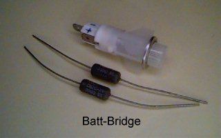
How it works: The Batt-Bridge divides the pack in half, and compares the voltage of each half. When the two halves are equal (within 1 volt or less), a green LED is lit. If a cell goes dead or begins overcharging somewhere in the pack, its voltage typically changes by more than a volt. This imbalance lights one of two bright red LEDs to tell you which half of the pack is low.
D1 is a standard brightness green LED. D2 and D3 should be ultrabright red LEDs for best visibility. R1 and R2 should be identical resistors, chosen to provide about 10ma at your pack voltage. The current sets the sensitivity and brightness of the LEDs.
Construction: Mount the LEDs in a pilot light holder.
Install it on the dashboard where the driver can easily see it,
and where it won't be washed out by direct sunlight. Mount the
resistors at the battery terminal ends of the wires, so they will
limit the current in case of shorts.
EV Circuits: The Zener-Lamp Shunt Regulator for Lead-Acid Batteries
The Batt-Bridge tells you that some batteries in your pack are less charged than others. With flooded batteries you can overcharge to bring up the low batteries, and replace the water lost in the ones that were already full. But if you overcharge sealed batteries, it shortens their life.
The Zener-Lamp regulator is intended for sealed 12v lead-acid batteries (though it can be adapted for other types). It bypasses excess charging current on full batteries, so the weaker ones can finish charging without overcharging those that are already full. It's a budget regulator, so even cheapskates won't have an excuse to murder their batteries because a real BMS (Battery Management System) would cost them too much.
How it works: Two zener diodes set the voltage above which it bypasses current. 6.2v and 6.8v zeners will bypass above 13v (full charge for a 12v battery). A #PR2 or #43 2.5v 0.5a lamp limits the current, provides a visual indication when it is bypassing, and acts as a fuse in case of overvoltage, miswiring, or component failures. The 10 ohm resistor is a backup in case the lamp fails.
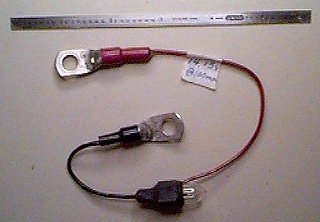
Construction: The zeners get hot! Mount them in large copper ring terminals for #6 wire. Fill the body with a thermally conductive epoxy (like JB Weld) to transfer the heat to the battery terminals. Solder the lamp and resistor in parallel. Connect them to the other ends of the zeners with short wires. Cover the connections with heat shrink tubing and epoxy to waterproof them.
Use: Near the end of a charge cycle, the lamps will begin
to light. Set up your charger to be at a low current (like 0.5
amp) at this time. At this current, each hour you charge puts an
extra 0.5 amphours into the low batteries whose lamps aren't lit.
The pack is balanced when all the lights are glowing to some
degree. This may take many hours on an out-of-balance pack. Once
balanced, subsequent charges should take under an hour to reach
this state.
EV Circuits: The Doubler 12v to 24v Contactor Driver
Contactors are expensive, and their coils use a lot of power. This can load down your 12v system, and the coils run hot. The Doubler cuts coil power by 4:1, by using less expensive contactors with 24v coils (common in industrial EVs and the surplus market). It doubles your 12v to 24v to pull in the contactor quickly. It then holds the contactor on with 12v, using only 1/4 the power. This lightens the load on your 12v system, and the coil runs cool for longer life. It also allows an intermittent-duty coil (which burns up if left on continuously) to be used for continuous-duty applications. For example:
 Albright SW-200 contactor with 12v coil:
How it works: The "Switch" is whatever your EV uses to control the contactor. It can be the ignition keyswitch, a relay, or the solid state output from a controller like the Zilla. When the switch is off, capacitor C1 charges through lamp I1 and Schottky diode D2. C1 quickly charges, and the current falls to zero. MOSFET Q1 is off because its gate is grounded by R1, the contactor coil, and D2.
When the switch closes, R1 turns Q1 on. This grounds the + end of C1, and lights indicator I1. Since C1 was charged to 12v, its - end is now at -12v. D2 blocks, so the contactor coil has +24v across it and pulls in. C1 quickly discharges, and the voltage across it falls to zero. The coil is then held on at 12v by current flowing through the switch and D2. Q1 stays on, so I1 stays lit.
When the switch turns off, the coil's inductive "kick" is clamped at -24v by zener D1. R1 turns Q1 off, and zener D3 protects the gate of Q1. C1 now recharges through I1 for the next switch turn-on.
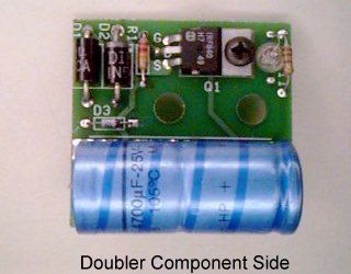
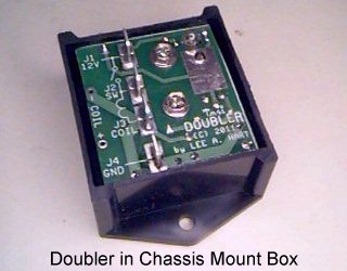
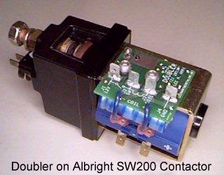
Construction: A bare PC board, parts kit, and assembled units are available. The board has holes to mount on an Albright SW180, SW190, and SW200 series contactors (or equivalent), or can be mounted separately in a plastic enclosure. The manual is available here in PDF format.
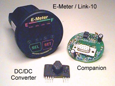 EV Circuits: The Companion Power and Data Isolator for the E-Meter and Link-10 Meters
The Cruising Equipment E-Meter and Heart Interface/Xantrex Link-10 and Link-Lite are popular high-quality meters used in many EVs. They display the voltage, current, state of charge, amphours in/out, KWH, time, temperature, and other factors. They can also send this data serially to your computer for data logging and analysis. This information is very useful for monitoring the health of your batteries, and extending their life.
However, the E-meter and Link-10 were originally designed for grounded 12v or 24v batteries. As such, they have a few shortcomings when used in EVs:
Adding all of this externally can easily add $200 to the cost of the meter. The Companion is a simple circuit board that includes all these functions (prescaler, isolated power supply, and isolated data output) at a much lower price. It simplifies installation and eliminates wiring errors. It mounts on the back of the meter, without increasing the depth behind the panel or extra little boxes. Build it yourself from the schematic. Bare boards, kit versions, and assembled Companions are also available.
How it works: R1, R2, R3, C1, and D1 are the Prescaler. If the pack is connected to W1, R1 scales the meter to read 0-100v. If the pack is connected to W2, R1-R3 scale the meter to read 0-500v. The meter has a configuration option to show the correct voltage with the prescaler connected. C1 is a noise filter (EV packs can be very noisy). D1 protects the meter from reversed or excessive voltages.
U3, C3, C4, and F1 are the isolated power supply. The heart of it is DC/DC converter U3. It has an 8-16vdc input, and a 24v 100ma output isolated to 3500v. The capacitors filter out noise. Fuse F1 protects against excessive voltage or reverse polarity inputs.
U1, U2, R4, R5, and C2 provide the optically isolated data output. Two optocouplers are used for a symmetric output with equal rise/fall times, to prevent distortion or errors. The resistors limit the LED current, and C1 speeds up the switching for sharp clean edges. The output of the optocouplers gets its negative supply from the serial data output of the PC (which is otherwise unused), and its positive supply from the 12v system that powers U3 and the meter. The data output thus has standard +/-12v RS-232 levels.
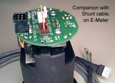
Construction: Everything mounts on a 1.9" diameter round PC board. Headers J2 and J3 use wirewrap pins, so the long tails reach the meter's screw terminal strip. U3 is socketed, so it can be plugged in after the screws are tightened. RS-232 connector P1 is taken apart and shortened, to avoid adding depth. Two screws secure it to the meter for additional support. (Note: Even if you bought your E-Meter/Link-10 without the serial option, it will probably have everything for it installed except the RS-232 connector itself. When you order a Companion, this connector is included in case your meter doesn't have one.)
Use: A shielded well-insulated shunt cable connects J2 to the shunt. A prewired 6' cable is supplied to prevent miswiring. The two ring terminals at the end connect to the small screws on the shunt.
The red wire to W1 or W2 should be well insulated, as it connects to the pack. If this wire is long, install a fuse at the battery end in case the wire ever shorts to ground.
The cable plugged into J1 provides +12v power, ground, and serial data output. A 3' cable is provided, but any length can be used. Separating J1 from J2 and J3 and using different connectors makes it impossible to mix up high voltage with the low voltage grounded wiring.
J3 is only used for options, such as a remote temperature sensor or alarm outputs.
High Voltage DC Relays and Contactors
You may have noticed that when you open a circuit (with a switch, relay, contactor, connector, or whatever), you get a spark. A little arcing is inevitable. But if it is not limited, it will shorten the life of the switching device, or even destroy it and leave the load still powered!
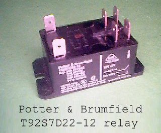
Switches, relays and contactors have voltage and current ratings, either printed on them, or listed in their data sheets. They can be pretty confusing! For example, here are the ratings printed on a Potter and Brumfield T92S7D22-12 relay:
Even more ratings are provided on the data sheet. But you don't need to be a contact engineer to understand all of this. It's sufficient to learn the basics, so you can pick a suitable contact for what you want to switch.
UL, CSA, and VDE are safety regulatory agencies. These codes tell you that someone other than the manufacturer has tested this part, and certifies that the ratings are honest. To get agency ratings, the part has to be able to switch the specified loads for 100,000 cycles. If you don't see any agency markings, the manufacturer is free to make up anything he likes. You'll often find absurdly high ratings on parts with no agency testing or confirmation. For example, automotive grade relays have no agency listings, and may only be able to switch their rated loads for 10,000 cycles... or less!
Let's look at the AC ratings. The higher the voltage, the lower the current it can carry. The first two values assume a resistive load. HP is "horsepower", i.e. an inductive load. Each horsepower is about 1000 watts; so 1HP is 1000w / 120v = 8.3 amps, and 3HP is 3000w / 240v = 12.5 amps. Inductive loads arc a lot more, so the current rating is roughly half as much when switching an inductive load.
Now look at the DC rating. Once you have more than about 30 volts across a contact, it will arc. Thus this relay only has a DC contact rating of 28 vdc at 20 amps. So why is the AC voltage rating so much higher? It's because AC voltages automatically go through zero 120 times a second at 60 Hz (or 100 times a second at 50 Hz). This automatically extinguishes the arc, so it won't last any longer than 8-10 milliseconds.
But on high voltage DC, once an arc starts it WON'T STOP until the contact spacing is very large, the current is very low, or some other mechanism stops it. The arc lets current keep flowing to the load, and also quickly destroys the contact. This particular relay has no provisions for switching high voltage DC; thus the low DC voltage rating.
The voltage rating of contacts in series add, because they increase the total open contact spacing. This is a double-pole relay, so you can wire both 28vdc contacts in series to switch 56vdc. Likewise, you can use a relay with four 30vdc contacts to switch 4 x 30vdc = 120vdc. Just make sure that ALL the contacts open and close at once (i.e. they are all part of the same switch or relay).
It also pays to look at the data sheet. Some switches and relays have higher DC voltage ratings at reduced currents. Schrack relays (now owned by Tyco) often have this data. For example, the Schrack PT570012 (Digikey PB912-ND) is a 4PDT relay with four 6 amp 120vac/30vdc contacts that the data sheet also rates at 300vdc at 1 amp.
You can also get relays and contactors specially designed to switch high voltage DC. Several methods are used:
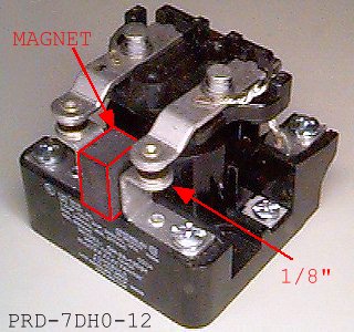
The Potter and Brumfield PRD-series is a common example. It is often used to switch EV chargers, heaters, and other DC loads up to 20 amps. It has two contacts, each rated at 125vdc that can be used in series to switch 250vdc. To get this rating, it has a blowout magnet, and extra-large contact spacings (see photo). It is available from multiple sources (Tyco, Deltrol, Magnecraft, etc.). The AC versions are far more common, so be sure to get one with the blowout magnet (such as the PRD-7DH0-12).
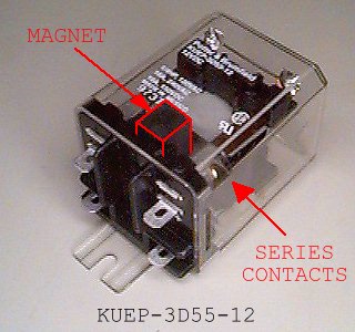
The smaller Potter and Brumfield KUEP-series is similar, but rated for 10 amps at 150vdc. It is useful for DC/DC converters and other smaller loads. It also has a blowout magnet (see photo), and two contacts pre-wired in series. Again, AC versions are much more common, so look for one with the magnet, like the KUEP-3D55-12.
I normally have these relays in stock for EV projects. If you need one, email me for details.
 Snubbers for High Voltage Switching
You often see a spark when you open a switch. A little arcing is inevitable. But if it is not limited, it will damage the switch and shorten its life. It can even cause the switch to fail shorted, and thus leave the load still powered! Snubbers are simple little circuits that reduce the stress on switches, so they can handle more power and last longer. Think of it as a "shock absorber" for electrical circuits. Snubbers are easy to add, and provide cheap insurance.
"Switch" means any device used to turn things on and off. It can be mechanical (switch, relay, contactor, fuse, circuit breaker, etc.) as well as solid state (diode, transistor, TRIAC, MOSFET, IGBT, etc.) Solid state devices are especially easy to damage -- just one instantaneous over-voltage event can destroy them!
Resistive Load: The type of load makes a big difference. With an ideal resistive load, the current simply starts when you turn it on, and stops when you turn it off. Suppose we are switching a 10 ohm resistive heater (Rload) across a 100 volt battery (see illustration). The switch voltage (red) is 0 volts when on, and 100 volts when off. The current (green) is 10 amps when on, and 0 amps when off. Simple!
Inductive Load: Inductive loads are very common. They include relay and contactor coils, motors, transformers, heaters with wirewound elements -- even just a length of wire has inductance. Inductors act like flywheels; they fight to keep the current from changing suddenly. Look at the illustration with inductance added to Rload. The current rises slowly at turn-on, as the inductance fights the change. If the load is a relay or contactor coil, this means it pulls in slower. It takes about 3 time constants (T=L/R) for the current to reach its final value. With the parts shown, T = L/R = 10mh/10ohm = 1 msec; so it takes 3 msec to reach 10 amps.
But look at that turn-off spike; it's over 350 volts! The inductor is trying to force the current to keep flowing despite the open switch. It "kicks" the voltage up and up, until the switch arcs or the transistor breaks down. In fact, an inductive load can easily produce peaks over 10 times the supply voltage. Unless your switching device has a huge voltage rating, it will fail.
Also notice the high-low-high-low ringing. Real circuits also inevitably have capacitance. This capacitance works with the inductance to form a resonant circuit that "rings" like a bell when struck by that high voltage "hammer". It causes interference, like a "pop" in your radio, or noise glitches in unrelated circuits.
The most common snubber is the "freewheel" diode (shown in yellow). A diode is connected across the load, oriented as shown to provide a path for the inductive current when the switch turns off. The diode clamps the voltage to no more than 1 volt above the supply (note the step to 101 volts). A diode snubber is cheap, easy, and effective. Use a diode with a voltage rating at least twice the supply voltage, and a current rating equal to the load current. In this example, use a 200v 10a diode.
The low clamping voltage has one drawback: It makes the load current slow to fall back to zero -- it's that 3 msec T=L/R time constant again. If you're driving a relay or contactor, a freewheel diode across its coil makes it turn off slowly, which is bad for its contact life. For a faster turn-off, you need to raise the clamping voltage. There are several ways:
Add a resistor in series with the diode. To clamp at 100v, R = 100v/10a = 10 ohms. When the switch turns off, the coil current diverts to the snubber diode and resistor, producing a 100v drop. The switch sees the sum of the supply voltage and clamp voltage (200v in this example). The total resistance has doubled to 20 ohms, so L/R is half as long; the load turns off twice as fast.
Add a zener diode with the desired clamping voltage in series with the diode (shown at right). When the switch turns off, the coil is held at the clamp voltage until it runs out of stored energy. Turn-off time is about twice as fast as a resistor-diode snubber with the same clamp voltage. The switch sees the sum of the supply voltage and zener voltage (100v + 100v = 200v in this example).
For a clamp voltage greater than the supply voltage, use a single bidirectional zener, ZNR, or MOV. Turn-off is very fast, and you only need one part. With a 150v part, the switch will see 100v + 150v = 250v peak. That's pretty high, so this approach is more practical for low-voltage circuits. For example, a 24v bidirectional zener in a 12v circuit will limit the switch to 36v peak.
Resistor-Capacitor Snubber: Note that the rise and fall times aren't quite instantaneous. Every switch (mechanical or solid state) takes time to open or close. As it changes, it briefly sees both part of the supply voltage, and part of the load current. A mechanical switch will arc during this time, when its contacts aren't quite fully opened. A transistor will dissipate power during this time, when its apparent resistance is changing between on (low) and off (high). How bad is it? Due to the inductive load in this circuit, the switch can be dissipating 100v x 10a = 1000 watts peak!
Diode snubbers clamp the voltage, but don't do anything about the rapid rate of rise in voltage. RC snubbers add capacitors to slow down the rate of rise, to give the switch time to fully turn off before it gets "hit" with the full off-state voltage.
An RC snubber is shown at the right. The snubber capacitor slows down the rise to 0.5 msec, to give the switch time to fully open before it sees the peak voltage. It also reduces the peak power in the switch, by delaying the voltage peak until the current has fallen to a low value. This puts less stress on the switch, so it runs cooler and lasts longer. The RC snubber still provides a fast decay in the load current, so relays and contactors will drop out quickly. It also lowers the LC resonant frequency, reducing noise.
The resistor in series with the capacitor has two jobs: It damps out the oscillations (like padding a bell). And it limits the peak current to charge the capacitor when the switch turns on (that's the green current spike you see at 1 msec).
Finding the "perfect" values for an RC snubber is challenging. For an analytical approach, look here. Or, you can use a circuit simulator, like LTspice. If you have an oscilloscope, or can see the contact, the Edisonian approach works; experiment with different values to minimize the peak voltage and arcing. Luckily, the values are not critical; capacitors from 0.01uF to 10uF, and resistors from 1 to 100 ohms work well for mechanical switches. In general, the higher the current, the higher the capacitance. The faster the switch, the lower the capacitance (so solid state switches use smaller capacitors). Then pick a resistance high enough to limit the peak turn-on current to something the switch can handle, but low enough to damp out the ringing.
RCD snubber: Diodes, resistors, and capacitors can be combined to make especially effective snubbers. The diode provides a predictable peak voltage limit, and removes that nasty turn-on current spike. The RC network slows the rate of rise, and gets rid of the ringing and noise. The most common RCD snubber circuit is shown at the right.
When the switch turns on, the diode is reverse-biased and so does not conduct. The resistor charges the capacitor to the supply voltage. Choose the resistor to keep this current low, so the switch turn-on current spike is negligible. After a few RC time constants, the capacitor voltage equals the load voltage and the snubber current falls to zero.
When the switch turns off, the load current shifts to the snubber. The diode gets forward biased, and conducts. The switch voltage rises slowly, as the inductive energy transfers to the capacitor. This limits the rate of rise in voltage, to give the switch time to fully turn off. When the inductor current falls to zero, the diode again blocks. The snubber resistor then slowly discharges the capacitor back to zero, so the circuit is ready for the next cycle.
The RCD snubber is a good way to maximize the power and life of a given switching device. It provides fast load turn-off, low stress on the switch, low noise, and the part values are relatively independent and easier to calculate:
Across the load, or across the switch: These examples show snubbers across the load. Snubbers can also be placed across the switch, if that's more convenient. But if the snubber fails shorted, it turns the load ON! There are special UL-recognized fuse resistors, MOVs and ZNRs (zener diode replacements), and X-type (across the line) and Y-type (line to ground) rated capacitors for this purpose that are guaranteed to fail open, and not explode or start fires if they fail.
Switching AC loads: The above assumes a DC load. If you're switching an AC load, the snubber circuit has to be bidirectional. Freewheel diodes and snubbers with unidirectional zeners won't work. You have to use RC snubbers, or snubbers with bidirectional zeners, MOVs, or ZNRs.
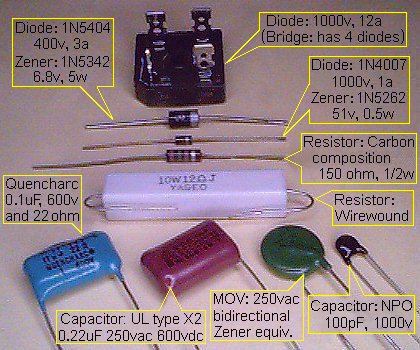
Parts for Snubbers: Snubbers need to handle high peak currents and voltages. Ordinary "cheap" resistors and capacitors are likely to fail. Types of parts to use:
I normally have these parts in stock for EV projects. If you
need some, email
me with a description of your load and I'll send you the parts for FREE with a donation to the Sunrise EV2 Project. Oh, and thanks for reading this far! :-)
No matter what kind of batteries you use, they will perform a lot worse when cold (just like people)! If you install about an inch of styrafoam insulation around your batteries, their own waste heat from daily driving and charging is usually enough to keep them warm. I put my batteries in such a box, with a removable lid. Leave the lid off in the summer, and put it on in the winter. A batt of fiberglass insulation is handy for insulating the lid, as it is nonconductive, won't trap vent gases, and molds itself around the terminals and wiring.
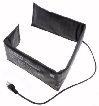
You'll need battery heaters if you don't drive every day, and live in a climate with weather below freezing. With 1" of insulation, you only need about 20-40 watts per square foot of battery area. With less insulation, more heat is needed. A typical battery heating blanket is shown at right. They come in various lengths and wattages, and sell in auto parts stores for $20-$60. It's a plastic bag, with about 1/4" of insulation inside and a long piece of nichrome resistance wire. The wire is attached to a thin sheet of aluminum foil, to hold it in position and (in theory) spread out the heat. The foil is connected to the AC line cord's ground wire in case something shorts.
You can use these as-is, but I've found they are a little too crude to work dependably. There is no thermostat, so the battery temperature is uncontrolled. There is no fuse, so if it gets wet or pinched it can even start a fire! And, it's not all that well protected from moisture or battery acid. For reliable operation, it is better to repackage them, and add a fuse and thermostat.
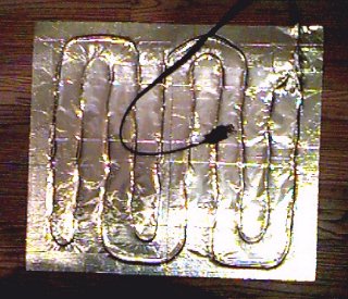
Here's an inexpensive way to do it. Cut a sheet of aluminum about the size of the floor of your battery box. Take the heater apart, carefully separate the resistance wire, and temporarily tape it to the aluminum sheet. Space the wires out evenly -- if they cross or even get too close to each other, you'll get a "hot spot" that will fail. Connect the ground wire to the aluminum sheet.
Get a 10-ounce tube of high-temperature silicone sealant (intended for sealing furnace ducts and chimney flues) from your local lumber company. Apply it to the wires with a caulk gun. Cover it with aluminum foil or a polyethylene plastic sheet, so you can push the sealant around and squeeze out the air pockets without making a mess. If this heater is for flooded batteries, apply plastic to both sides with the silicone sealant to prevent corrosion and ground fault leakage currents.
Silicone needs exposure to air and moisture to cure, so it will take a long time to fully set. But with the plastic or foil cover, you don't have to wait before handling and installing it. The left photo shows one of my repackaged battery heaters.
Lay a sheet of styrafoam in the bottom of your battery box. Place the heater on top of it, with the wire side down. Now place the batteries on top of that. The wires will sink slightly into the styrafoam, and won't be pinched or damaged by the weight of the batteries. The aluminum will spread the heat evenly over all the batteries.

Let's anthromorphize a bit, and consider lead-acid batteries as alive; like the family dog.
The usual reason you see a used EV that says "needs batteries" is because the previous owner treated the batteries cruelly. Whether by ignorance or laziness, some or all of the above guidelines were violated. But batteries are replaceable, and it usually means you can get the EV "cheap".
Such problems can be cured. A little detective work to fix the problems, and then some tender loving care will go a long way toward getting the longest life possible out of your next set of batteries.
So, how DO you treat your batteries to last? The most basic rule is that you can charge a lead-acid battery at any current you like until it reaches 2.4 volts per cell at 25 deg.C (77 deg.F). That's the familiar 7.2v per 6v battery, or 14.4v for a 12v battery. Below this voltage, essentially 100% of the current goes into charging the battery, so there is negligible heating or gassing.
Bulk stage: The battery won't reach 2.4v per cell until it is about 70-80% charged. Therefore, to charge the quickest, charge with as much current as your charger or AC line allows. If you (or your charger) keep adjusting to maintain maximum current, you're doing what is called "constant current" or the "bulk" charging stage.
Above 2.4v/cell, the battery starts to gas and generate heat. You need to limit the voltage and time spent above this voltage, or you will use water and shorten the life of your batteries.
Absorption or Finish stage: At 2.4v/cell, the charger needs to slow down so the voltage does not exceed 2.4v/cell. It puts in the last 20-30% of the energy needed to reach 100% charged.
The current will gradually fall as the battery reaches 100% charged. When the current falls to about 2% of the battery's 20-hour amp-hour capacity rating expressed as amps (i.e. 2% of 250 amp-hrs = 5 amps), the battery is 100% charged. This stage has a number of names, such as "constant voltage", "acceptance", "absorption" or "finish".
Off: The charger can be turned off at this point. This is all you need to charge on a daily basis.
Float or Maintenance stage (optional): If you expect the battery to sit unused for a long time (months or years), you can apply a lower voltage of 2.2-2.3v/cell (13.2-13.8v on a 12v battery). This is below the "gassing" voltage", so water usage is minimal.
Equalization stage (optional): All the cells in a battery are not identical; they will have slightly different amp-hour capacities and self-discharge rates, and so will drift to slightly different states of charge. These differences get larger as the batteries age and get cycled. So once in a while, you need to deliberately overcharge the battery slightly so the weaker cells are brought up to full charge, too. This is called "equalization."
Equalization can shorten the life of the batteries, so you don't want to do it any more than you have to. But if you don't do it enough, the cells will get so far apart that one goes dead when the others are still half charged. This is bad. If you keep using a battery with one less-charged cell, it will go dead first, and get reversed (charged backwards by the current flowing through it from the other cells) and be damaged.
To equalize, charge as above until the current falls to 2% at 2.4v/cell (this is roughly 100% charged). Then continue charging at the 2% current until the voltage quits rising, or reaches about 2.5v/cell for sealed, or 2.6v per cell for flooded. New batteries will get there; old batteries will level off somewhere earlier.
For a flooded battery, you want the equalization current to be about 2% of the 20 hour amp-hour capacity (C20) expressed in amps, and the amp-hours should be about 4% of its amp-hour capacity. For example, a golf car battery is about 250 amp-hours, so that's 5 amps for 2 hours (10 amp-hours).
Remember, equalization is hard on batteries. Do it once a month or less. If they haven't been equalized in a long time, it's better to equalize for an hour or two after every charge for a few cycles rather than for many hours after one.
All this is of course general information. Flooded lead-acids can be charged "harder" (because you can replace water lost by gassing), and gels need to be charged at lower voltages. If you have better data from the manufacturer of your particular battery, use it. But I think you will find all of them to be variations on the same theme.
You can do all this manually, with a simple tapped transformer, or variac, or variable power supply. A manual charger should thus have at least two meters; battery volts and battery amps. A third meter (AC line current) is nice to avoid tripping circuit breakers or fuses.
It should also have a knob or switches to adjust the rate of charging. Volts and amps are related by Ohm's law; adjusting one inevitably adjusts the other. So it doesn't matter if the charger is adjusting current or voltage; either one is basically adjusting the rate at which the battery charges.
Unless you NEVER make a mistake, it's wise to include a timer that will automatically turn off the charger (in case there's something good on TV and you forget to turn it off)!
If all this seems like too much work, now you know why people buy automatic chargers. Most cheap consumer-grade battery chargers are Taper chargers. It's basically just a fixed transformer and rectifier, maybe with an ammeter or an LED or two. The designer has picked the transformer and circuit resistance so the charging current just happens to be a safe maximum when the batteries are deeply discharged, and just happens to "taper off" to that 2% figure when the batteries reach 2.4v/cell.
Taper chargers are slow, because they spend so much time at lower currents. It will take 8-16 hours to reach full charge with one. That happens to be convenient for overnight charging.
But if you leave it on even longer, its voltage will continue to rise (and the current continue to fall) and it will do a half-assed equalization. If you leave it on continuously, it will equalize your batteries to death. Thus it is a good idea to include a timer that will shut it off after some reasonable number of hours.
Even with the lower voltage, it will still eventually overcharge and dry out a battery over a period of months or years. Float chargers are mainly used for long-term storage and maintenance (like to keep the battery charged in a UPS, or in a boat or RV over the winter).
Some people erroneously call any small charger a "trickle" charger. Hopefully, what they really mean is that it's a float charger.
Chargers have been greatly improved with electronics to regulate the charging voltage, current, and time. They can automate the whole bulk/finish/equalize/float process described above. A typical "smart" charger can:
A good one can also correct for temperature, age, and type of battery (Flooded, AGM, or Gel).
But be warned! There is a lot of hype and utter junk being sold as "smart" chargers. The sellers know most people won't actually test it, to see what it really does. My advice is to put a meter on it, and see what it actually does before trusting it with your expensive batteries!
The voltages mentioned above all change with temperature. Voltage falls about 0.003 volts per cell for each degree C increase (and rises at the same rate for a decrease in temperature). If you ignore this, or your "automatic" charger does not sense battery temperature, you will apply too much voltage to hot batteries and fry them; or too little voltage to cold batteries and so not fully charge them.
As your batteries age, their end-of-charge voltage gradually falls, their end-of-charge current gradually rises, and their amp-hour capacity slowly drops. Barring abuse, this is normal, inevitable, and not reversible.
If your charger blindly tries to bring old batteries up to the same voltage or current as new ones, it will charge too long, and overcharge them. So, the best charging algorithms for old batteries are ones that count amp-hours, or look for the voltage to stop rising (dv/dt) or for the current to stop falling (di/dt) at end of charge.
Failing to take these factors into account is what causes an old pack to "suddenly" die when it just has a weak battery or the pack gets old.
Although the "magic" battery additives and "desulfator" salesmen would have you believe otherwise, the changes in characteristics with age are usually not reversible. They are caused by:
Don't waste your money on "desulfators". Sulfation is the normal chemical reaction that occurs when a battery is discharged. It is reversed simply by proper charging. If a battery is good, but completely dead (less than half its rated voltage even with no load), essentially all the lead and sulfuric acid have been converted into lead sulfate and water. Water is such a poor conductor that it won't charge normally. Instead, charge it from a higher voltage source with a resistance in series to limit the current.
For example, if a 12v battery is less than 6v, charge it with a 24v power supply and a car tail-light in series. The battery voltage will rise to almost 24v, and the current will initially be so low that the tail-light is off or barely glows. But the current will slowly rise over time (it may take days!) as the lead sulfate on the plates gradually turns back into lead and sulfuric acid. When the car tail-light finally lights up normally, then you can charge the battery normally on a 12v charger. It will have less capacity after such a near-death experience; but may still be useful.
Don't leave a "trickle" or "float charger" on continuously. That's not the best way to maintain them, as they will slowly gas away all the water. For example, the batteries in a UPS are typically "float charged" at about 13.7v, and so are shot after a few years even if they never get used.
The best way to store lead-acid batteries is to fully charge them normally as described above. Then just let the batteries sit with no load, and no charging. Make sure everything is disconnected, with no sneaky "vampire" loads.
Then every 1-3 months (depending on how good the batteries are), put them on charge for an hour or so. For good batteries, it won't even take an hour for the voltage to peak again (i.e. they have a low self-discharge rate). AGMs and Gels have lower self-discharge rates, and so can sit this way for 3-6 months.
If you work with EVs, you need a way to test batteries. I've used all sorts of setups over the years, ranging from jury-rigged parts from my junkbox to sophisticated systems like my Battery Balancer. There are also commercial products, ranging from cheap junk for testing hobby R/C batteries to very expensive professional-grade systems.
I think the most useful ones have been my home-made load testers. They are simple enough to be cheap and easy to build. They are rugged enough to handle high current for long periods of time. Best of all, I know what they are doing, so I know what the test results mean. I've described them before on the EV Discussion List, but here's a more complete description in case you'd like to build your own.
A "load tester" basically consists of the following:
Here's an example: The tester pictured at the right was built in the discarded case from an inexpensive 120vac 1500 watt heater. The case was gutted, and nothing was kept but the fan switch. I installed a 12vdc muffin fan in place of the original 120vac fan. A large aluminum extruded heatsink was mounted in front of the fan. A big 40 amp automotive relay switches the load (the little Fan switch would die trying to switch high current DC). The load was made from a couple dozen surplus 25 watt power resistors in anodized aluminum cases, screwed to the heatsink for cooling. These resistors are wired to the FAN switch so I can select the load current. The FAN switch had 5 positions; Off, Fan, Low, Med, and High. I wired these positions to the resistors to provide the following loads for a 12v battery:
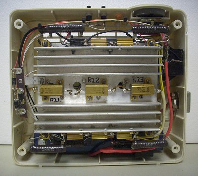
The left picture is the view inside. The heatsink with all the resistors is in the middle. A 4.7" square 12vdc fan is hidden behind it. The CHARGE and DISCHARGE buttons are at the top, and the FAN switch to set the load current is on the top right. The relay is the black box at the right, with a 30 amp circuit breaker just below it in case anything goes wrong.
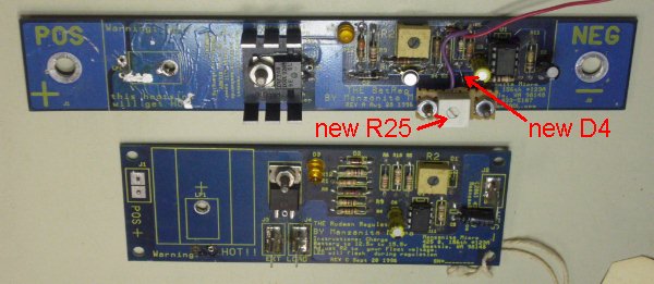
Voltage is sensed by a modified Manzanita Micro "Rudman Regulator" (barely visible at the bottom of the case). These are normally used to balance or equalize 12v lead-acid batteries. It switches a 7.5 ohm load resistor across the battery if it exceeds a "fully charged" voltage set by a trimpot (i.e. 14.8v). It switches off when the voltage drops about 50 millivolts from this. I modified an old "rev.A" Rudman Regulator to make its turn-off adjustable with a trimpot to a "fully discharged" voltage (i.e. 10.5v). I also added a pair of pushbuttons to manually switch it ON and OFF. The modifications are very simple; only few parts are added.
The relay coil is wired to the regulator's external load terminals. The regulator's 7.5 ohm load resistor was removed (they tend to burn up). The relay contacts switch the battery between the charger and the load resistors. In operation, the regulator switches the battery to the charger until it reaches the "fully charged" voltage; then to the load until it reaches the "fully discharged" voltage; and then repeats.
     ____/\/\/\____________________________________
    |      R27          |  D4      R25             |
    |      1K           | 1N270   100K             |
    O                   |__|/|___/\/\/\__          O
     / S2               |  |\|      ^           S3  /
    O  DISCHARGE        |           |       CHARGE O
 ___|___________________|___________|___________   |
|J1 |                   |           o ___    J2 |  |
| |_|                   |        R5 || R2|    |_|__|
| |                     |      1meg ||___|    | |
|POS    LP1             |___________o        NEG|
|    (removed)                                  |
|               EXT  LOAD                       |
|                J3   J4                        |
|            POS _|   |_     Rudman Regulator   |
|_______________|_|___|_|_______________________|
                |       |
             D5 |__|/|__|
         1N4001 |  |\|  |
                |       |
                |_|_|_|_|
                   K1
       Potter & Brumfield VF4-45F11
     12vdc coil, 40/30a SPDT contacts
Adjustment: The original trimpot on the Rudman Regulator, R2, works as before. It adjusts the voltage at which the regulator turns on (the high, or fully-charged voltage). New trimpot R25 adjusts the voltage at which the regulator turns off (the low, or fully-discharged voltage). The range of adjustment are as follows (based on my unit):
            Turn-On Voltage         Turn-Off Voltage
R2 at -->  min   center   max      min   center   max
          ------ ------ ------    ------ ------ ------
R25: min  13.38v 14.22v 15.45v     9.85v  9.87v 10.00v
  center  13.38v 14.22v 15.45v    12.88v 13.45v 14.41v
     max  13.39v 14.22v 15.46v    13.13v 13.76v 14.82v
Instrumentation: I used a Cruising Equipment / Heart Interface / Xantrex "E-meter" with RS-232 port, and an old XT PC computer for data logging. A digital multimeter with RS-232 port could serve as well. I wrote a QuickBASIC program to display, print, and save the data to disk. I built this setup over 20 years ago, and still use it regularly!
Click here for my QuickBASIC program to print, graph, and log data from the E-meter / Link-10.
Operation: Connect a battery, and a charger. Set up the computer to log the data (or use a clipboard, pencil, clock, and meter). Set the FAN switch for the desired discharge current. Press the CHARGE button. The Rudman regulator thinks the battery has fallen below its lower limit, and turns off. This drops out the relay, which in turn connects the charger to the battery.
The charger charges the battery. When the battery reaches 14.8v (or whatever you set with the original trimpot on the board), the regulator turns on. This pulls in the relay, whose contacts disconnect the charger and connect the load resistors.
The load resistors discharge the battery. When the battery reaches 10.5v (or whatever you set with the new trimpot), the regulator turns off. The relay drops out, which disconnects the load and connects the charger.
The charge-discharge cycle repeats continuously. Or, turn off the FAN switch while charging to end the current cycle with the battery fully charged. Or turn off the charger while discharging to end with the battery fully discharged.
Specific Gravity  Volts/Cell  6v Battery  8v Battery  12v Battery  State of Charge
     1.260        2.12-2.15v  6.3-6.45v   8.4-8.6v    12.6-12.9v   100% (full)
     1.220        2.06v       6.18v       8.25v       12.36v        75%
     1.180        2.03v       6.09v       8.12v       12.18v        50%
     1.140        1.99v       5.97v       7.96v       11.94v        25%
     1.100        1.97v       5.91v       7.88v       11.82v         0% (dead)

     0.030        0.017v      0.05v       0.067v      0.1v   <-- maximum variation
                                                                 between cells or
                                                                 batteries
Notes:
   1. Measure after sitting without charging or discharging for at least 8 hours.
   2. AGM and starting battery voltages will be a little higher.
   3. Old battery voltages will be a little lower.
                             typical lead-acid battery life (cycles)
Dept of Discharge(%)  ----flooded-----  ------gel-------  -------agm-------
                       (Trojan T-105)   (Deka Dominator)  (Deka Intimidator)
        100%           600 x 1.0 = 600   450 x 1.0 = 450   150 x 1.0 = 150
         80%           800 x 0.8 = 640   600 x 0.8 = 480   200 x 0.8 = 160
         50%          1500 x 0.5 = 750  1000 x 0.5 = 500   370 x 0.5 = 185
         25%          2500 x .25 = 625  2100 x .25 = 525   925 x .25 = 231
         10%          5500 x 0.1 = 550  5700 x  .1 = 570  3100 x 0.1 = 310
Notes:
   1. Cycle life depends on type of battery, depth of discharge, and discharge current.
   2. The shallower the discharge, the greater the cycle life.
   3. Minimum cost per mile occurs when cycles x DOD% is at its maximum.
The Sunrise EV2 Project, © 2007-2023 by Lee A. Hart.
Created 3/15/2012. Last update 8/10/2023.
Go to TOP ........ Go to HOME ........ Questions? Comments? Want
to help? CONTACT US!
Web hosting provided by Innovative Computers